

![]()

MVP Matrix is the shorthand of Model, View and Projection matrices. Model matrix represents the 3d model’s transformation from object space to world space. View matrix represents the transformation of the 3d model from the world space to the camera(view) space. Projection(Clip) matrix represents the transformation of the 3d model from camera space to clip(screen) space.
Model matrix is used for the transformation of 3D Models from model space(also called object/local space) to the world space. It includes Translation, Rotation, and Scale. For more Detail see post Matrix SRT
View matrix is used for the transformation of 3D Models from world space to view(camera) space. This is called view transformation. As we all known, there are two major coordinate system, right hand coordinate system, and left hand coordinate system. In Unity game engine, it uses left hand coordinate system, but in the view space, it will be coverted to right hand coordinate system.
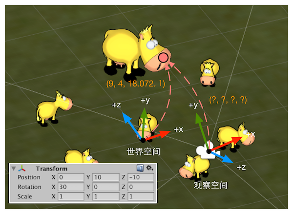
In order to get the model’s position in view space, we can place the origin of the camera at the origin of the world coordinate. based on the Transform Component in above picture, the transformation of camera in world space order is rotate (30,0,0), then translate(0,10,-10). so in order to move the camera’s position back to the world origin, we need to do the inverse transformation, first translate(0,-10,10) then rotate(-30,0,0). we can get a matrix $M_{view^\prime}$
\begin{equation} M_{view^\prime} = \begin{bmatrix} 1 & 0 & 0 & 0 \
0 & cos(-30) & -sin(-30) & 0 \
0 & sin(-30) & cos(-30) & 0 \
0 & 0 & 0 & 1 \end{bmatrix} \begin{bmatrix} 1 & 0 & 0 & 0 \
0 & 1 & 0 & -10 \
0 & 0 & 1 & 10 \
0 & 0 & 0 & 1 \end{bmatrix} \end{equation}
However, due to the view space’s coordinate system is changed to right hand coordinate system , so we have to invert the z component by mulitply another matrix $M_{negatez}$
\begin{equation} M_{view} = M_{negatez}M_{view^\prime} =
\begin{bmatrix} 1 & 0 & 0 & 0 \
0 & 1 & 0 & 0 \
0 & 0 & -1 & 0 \
0 & 0 & 0 & 1 \end{bmatrix} M_{view^\prime} \end{equation}
Finally, we can use this $M_{view}$ muiltiply the 3d model’s world position $P_{world} = (9,4,18.072,1)$ to get the 3d model’s position in view space $P_{view}$.
\begin{equation} P_{view}^T = M_{view}P_{world}^T = M_{view} \begin{bmatrix} 9 \
4 \
18.072 \
1 \end{bmatrix} \end{equation}
Projection matrix is also called clip matrix which is used for the transformation of 3D Models from view space to clip space, then perform standard homogeneous division, also known as perspective division to get the Normalized Device Coordinates(NDC). Finally project on to screen which is known as screen space. Different from view space, the screen space is a 2-Dimensional space.
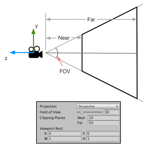
The goal of clip space is to clip the render objects based on the view frustum. everything inside this view frustum will be rendered onto screen, others will be clipped. There are 2 types of Projection, one is Perspective projection, another is orthographic projection(shown in below image).

Perspective projection is characterized by the near large far small. There are 4 input parameters in perspective projection, Field of View(FOV), Aspect, Near , and Far.
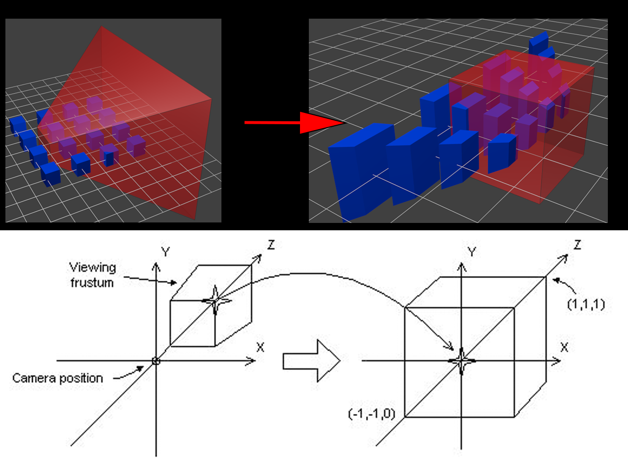
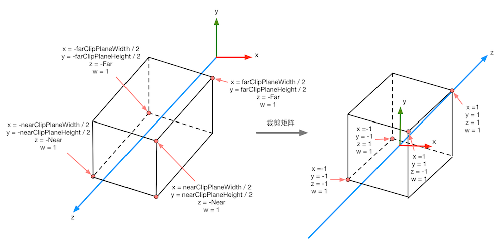
The purpose of perspective projection is to transform the view frustum into a cuboid for eaier clipping. After the transformation, the upper right corner of the near clipping plane of the view frustum will become the center of the front plane of the cuboid. This is known as Normalized Device Coordinates(NDC)
As can be seen from below figure, the transformation process is to enlarge the smaller part and shrink the larger part to form the final cuboid. That’s why the projection transformation is going to have a smaller effect.The x-coordinate range after transformation is [-1, 1], the y-coordinate range is [-1, 1], and the z-coordinate range is [-1, 1] (DirectX is slightly different, and the z-value range is [0, 1]).
Based on above infomation, we can get the perpective projection matrix $M_{frustum}$.
\begin{equation} M_{persp} = \begin{bmatrix} \frac{cot\frac{FOV}{2}}{Aspect} & 0 & 0 & 0 \
0 & cot\frac{FOV}{2} & 0 & 0 \
0 & 0 & -\frac{Far+Near}{Far-Near} & -\frac{2\cdot Near\cdot Far}{Far-Near} \
0 & 0 & -1 & 0 \end{bmatrix} \end{equation}
Then we can get $P_{clip}$ by multiply $P_{view}$.
\[P_{clip} = M_{persp}P_{view}\]For the derivation method, refer to the this Link
Step 1:

Based on above image,, calculating $y’$. $P = (y,z)$ and $P’ = (y’,z’)$. We can get
\[z = -cot(\frac{FOV_y}{2})\]Also, because $\Delta PAO$ and $\Delta P’A’O$ are similiar triangle, so
\[\frac{y}{z} = \frac{y'}{z'}, z' = -cot(\frac{FOV_y}{2})\] \[y'= \frac{y}{z} z' = -\frac{y}{z} \cdot cot(\frac{FOV_y}{2})\]Step 2:

We can use the same method to calculate the top view(see img above) to get
$ x’= -\frac{x}{z} cot(\frac{FOV_x}{2}) $$
However, we dont know the $FOV_x$, but we can based on $FOV_y$ and the Aspect of the screen to calculate
\[Aspect = \frac{W}{H} = \frac{tan(\frac{FOV_x}{2})z'}{tan(\frac{FOV_y}{2})z'} = \frac{cot(\frac{FOV_x}{2})}{cot(\frac{FOV_y}{2})}\] \[cot(\frac{FOV_x}{2}) = \frac{cot(\frac{FOV_y}{2})}{Aspect}\]Based on above formulas to get x’
\[x' = -\frac{x}{z}cot(\frac{FOV_x}{2}) = -\frac{x}{z} \cdot \frac{cot(\frac{FOV_y}{2})}{Aspect}\]Step 3:
Combine above to get $P’$
\[p' = (x',y',z',1) = ( -\frac{x \cdot cot(\frac{FOV_y}{2}) }{z \cdot Aspect}, -\frac{y}{z} \cdot cot(\frac{FOV_y}{2}), z', 1 )\]However, $z’$ is still unknown. By the nature of the Homogeneous coordinates, if $w \neq 0$, then $(x,y,z,1) = (wx,wy,wz,w)$. We can use $P’$ multiply $-z$ to get \(P' = ( \frac{x \cdot cot(\frac{FOV_y}{2}) }{Aspect}, ycot(\frac{FOV_y}{2}), -zz', -z )\)
Step 4:
Observing the components of P’ we got above, we can find P’ actually can be calculated by using P post-multiply a Matrix, $M_{proj}$.
\begin{equation} \begin{bmatrix} \frac{x \cdot cot(\frac{FOV_y}{2}) }{Aspect} \
ycot(\frac{FOV_y}{2}) \
-zz’ \
-z \end{bmatrix} = M_{proj} \begin{bmatrix} x \
y \
z \
1 \end{bmatrix} =
\begin{bmatrix} \frac{cot(\frac{FOV_y}{2}) }{Aspect} & 0 & 0 & 0 \
0 & cot(\frac{FOV_y}{2}) & 0 & 0 \
m_1 & m_2 & m_3 & m_4 \
0 & 0 & -1 & 0 \end{bmatrix} \begin{bmatrix} x \
y \
z \
1 \end{bmatrix} \end{equation}
So, if we can get m1, m2, m3, m4, then we can get the projection matrix M_proj. Firsly we know that the every point in the projection plane has the same z value which means z has no relationship with x or y. so we can get only when $m_1 = m_2 = 0$, we can make sure xy won’t influence projection point z’. We can get \(m_3z + m_4 = -zz'\)
In Direct3D platform after projection the range of z’ is [-1,0], we can get z’(-Far) after the z-projection in the far plane is -1, and z’(-Near) after the z-projection in the near plane is 0. Therefore we can get a set of equations
\[\begin{cases} m_3(-Far)+m_4 = Far(-1)\\ m_3(-Near)+m_4 = Near \cdot 0 \end{cases}\]After calculate, we can get
\[\begin{cases} m_3 = \frac{Far}{Far-Near}\\ m_4 = \frac{NearFar}{Far - Near} \end{cases}\]Then Plug $m_1$ $m_2$ $m_3$ $m_4$ into $M_{proj}$, we can get M_{tempProj}:
\begin{equation} M_{tempProj} =
\begin{bmatrix} \frac{cot(\frac{FOV_y}{2}) }{Aspect} & 0 & 0 & 0 \
0 & cot(\frac{FOV_y}{2}) & 0 & 0 \
0 & 0 & \frac{Far}{Far-Near} & \frac{NearFar}{Far - Near} \
0 & 0 & -1 & 0 \end{bmatrix} \end{equation}
Step 5.1 Unity Projection Matrix in Direct3D Platform :
In the vertex operation stage, projection transformation can be considered as the last step, then the vertices will go into rasterization stage, in rasterization stage, In Unity, the clip space uses Left Hand Coordinate, so it is necessary to convert back to left hand coordinate system. When x and y components of right hand coordinate system and left hand coordinate system has the same direction, then their z components are opposite. we can calculate it to get
\begin{equation} M_{proj} =
\begin{bmatrix} 1 & 0 & 0 & 0 \
0 & 1 & 0 & 0 \
0 & 0 & -1 & 0 \
0 & 0 & 0 & 1 \end{bmatrix} \begin{bmatrix} \frac{cot(\frac{FOV_y}{2}) }{Aspect} & 0 & 0 & 0 \
0 & cot(\frac{FOV_y}{2}) & 0 & 0 \
0 & 0 & \frac{Far}{Far-Near} & \frac{NearFar}{Far - Near} \
0 & 0 & -1 & 0 \end{bmatrix} = \begin{bmatrix} \frac{cot(\frac{FOV_y}{2}) }{Aspect} & 0 & 0 & 0 \
0 & cot(\frac{FOV_y}{2}) & 0 & 0 \
0 & 0 & \frac{Far}{Near-Far} & \frac{NearFar}{Far - Near} \
0 & 0 & -1 & 0 \end{bmatrix} \end{equation}
Step 5.2: Unity Projection Matrix in OpenGL Platform
Because the range of z’ in OpenGL platform is [-1,1]. We should scale the range of z from [-1,0] to [-1,1]. we can get z’(-Far) after the z-projection in the far plane is -1, and z’(-Near) after the z-projection in the near plane is 1. Therefore we can get a set of equations:
\[\begin{cases} m_3(-Far)+m_4 = Far(-1)\\ m_3(-Near)+m_4 = Near \cdot 1 \end{cases}\]After calculate, we can get
\[\begin{cases} m_3 = \frac{Near+Far}{Far-Near}\\ m_4 = \frac{2NearFar}{Far - Near} \end{cases}\]Then plug them into $M_{tempProj}$, we can get:
\begin{equation} M_{proj} =
\begin{bmatrix} 1 & 0 & 0 & 0 \
0 & 1 & 0 & 0 \
0 & 0 & -1 & 0 \
0 & 0 & 0 & 1 \end{bmatrix} \begin{bmatrix} \frac{cot(\frac{FOV_y}{2}) }{Aspect} & 0 & 0 & 0 \
0 & cot(\frac{FOV_y}{2}) & 0 & 0 \
0 & 0 & \frac{Near+Far}{Far-Near} & \frac{2NearFar}{Far - Near} \
0 & 0 & -1 & 0 \end{bmatrix} = \begin{bmatrix} \frac{cot(\frac{FOV_y}{2}) }{Aspect} & 0 & 0 & 0 \
0 & cot(\frac{FOV_y}{2}) & 0 & 0 \
0 & 0 & -\frac{Far+Near}{Far-Near} & -\frac{2NearFar}{Far - Near} \
0 & 0 & -1 & 0 \end{bmatrix} \end{equation}
The view frustum of orthographic projection is a cuboid, so it will be easier to calculate the transformation matrix, $M_{ortho}$.
Similarly, we need to scale the orthogonal projection matrix’s x,y,z components to the range of -1, 1 become Normalized Device Coordinates(NDC).
\begin{equation} M_{ortho} = \begin{bmatrix} \frac{1}{Aspect\cdot Size} & 0 & 0 & 0 \
0 & \frac{1}{Size} & 0 & 0 \
0 & 0 & -\frac{2}{Far-Near} & -\frac{Near+Far}{Far-Near} \
0 & 0 & 0 & 1 \end{bmatrix} \end{equation}
Then we can get $P_{clip}$ by multiply $P_{view}$.
\[P_{clip} = M_{ortho}P_{view}\]End –Cheng Gu