

The pipeline of Graphic Rendering includes 3 stages: Application Stage –> Geometry Stage –> Rasterization Stage.
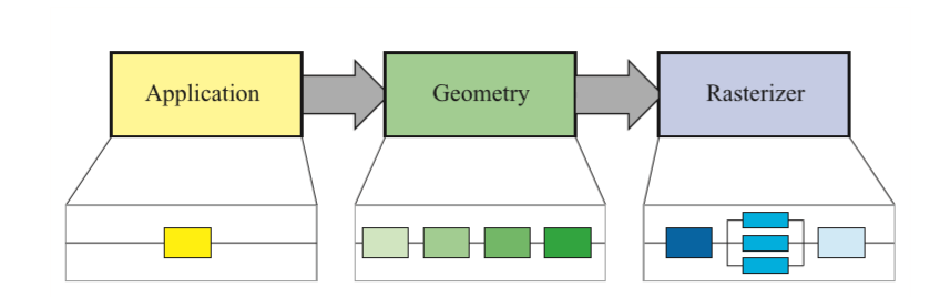
The start point of the rendering pipeline is CPU. In the Application Stage, the most important output is the geometry infomation which need to be rendered, called Rendering Primitives.
In this Stage, the developer has
3 Tasks:
Prepare the environment and camera's position. How many models are used in the environment, and which kinds of light sources are used in the scene.
In order to improve the performance of rendering, need to do the work of Culling, to get rid of unnecessary rendering process.
Need to set up the rendering state of each model, such as the materials , textures, shaders.
CPU will call DrawCall() to make GPU draw stuff on screen.
For example:

In Geometry Stage, the GPU will do the vertex operation through the received vertex data from the CPU.
The Process:
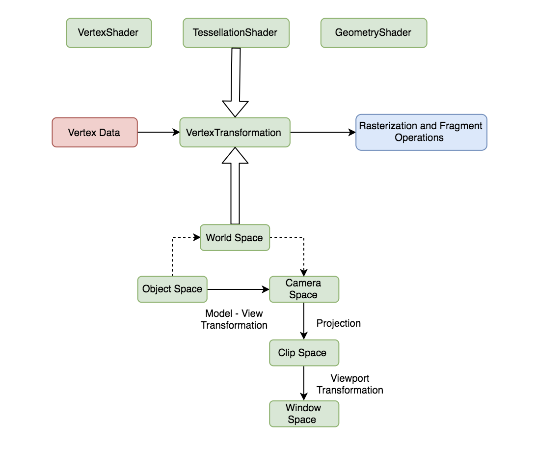
Vertex Shader: programmable , it is usually used to implement vertex space transformation, vertex shading and other functions.
Tesselation Shader: An optional shader for subdividing primitives (primitives are the basic units that make up an image, such as points, lines, surfaces, etc.).
Geometry Shader: An optional shader for polygon shading operations.
Clipping: this phase is configurable. The goal of this phase is to trim away the vertices that are not in the camera’s field of view and to remove the facets of certain trig elements.
Screen Mapping: This stage is not configurable and is not programmatic; it is responsible for converting the coordinates of each pixel to the screen coordinate system.
Meaning of_MVP (Model View Projection):
The vertices of a model are stored in the Object Space. The position and the orientation of each model are stored in World Space.
Before an object can be rendered, its vertices must be transformed into the Camera Space (also called View Space).
It is possible to transform vertices from object space directly into camera space by concatenating the matrices representing the transformations from object space to world space and from world space to camera space. The product of these transformations is called the Model-View Trasnformation. Once a model’s vertices have been transformed into camera space, they will also do a projection transformation to apply Perspective (the geometry becomes smaller as the distance from the camera increases).
In Rasterization Stage, GPU will use the data passed in the previous stage(Geometry stage) to produce pixels on the screen and render the final image.

The Process:
Triangle Setup: Calculating the Differences in triangular surfaces and other relevant data. complete fixed hardware operations.
Triangle Traversal: This stage checks whether each pixel is inside a triangle, and fragment is generated at this stage. Interpolation is usually used.
Fragment Shader: Fully programmable. Use interpolated shading data as input and output one or more color values for the next phase. At this stage, GPU execution can be controlled by programming. The most commonly used technology in this stage is texture technology.
Per-Fragment Operation: The Color value for each pixel is stored in the Color Buffer(a rectangular array of RGB colors) and merged at this stage. This stage is not completely programmable, but can be configured to produce different effects. In detail includes:
The pixel ownership (the only one can't be disabled): it simply determines whether a fragment lies in the region of the viewport that is currently visible on the display.
Scissor Test: An application may specify a rectangle in the viewport, called the scissor rectangle, to which rendering should be restricted. Any fragments falling outside the scissor rectangle are discarded.
Alpha Test: When the final color of a fragment is calculated, an application may also calculate an alpha value that usually represents the degree of transparency associated with the fragment. The alpha test compares the final alpha value of a fragment to a constant value that is preset by the application. The application can specifies what relationship between the two values (such as less than, greater than, or equal to) causes the test to pass. If the relationship is not satisfied, then the fragment is discarded.
Stencil Test: The stencil test reads the value stored in the Stencil Buffer(an offscreen buffer used to record the locations of the rendered primitive) at a fragment’s location and compares it to a value previously specified by the application. The stencil test passes only if a specific relationship is satisfied (e.g., the stencil value is equal to a particular value); otherwise, the stencil test fails, and the fragment is discarded.
Depth Test: The depth Test compares the final depth associated with a fragment to the value currently stored in the depth buffer, it is also called Z-Buffer. A z-buffer is the same size and shape as the color buffer, and for each pixel it stores the z-value to the currently closest primitive. This means that when a primitive is being rendered to a certain pixel, the z-value on that primitive at that pixel is being computed and compared to the contents of the z-buffer at the same pixel. If the new z-value is smaller than the z-value in the z-buffer, then the primitive that is being rendered is the one which is closer to the camera.
Blending: Once the pixel ownership test, scissor test, alpha test, stencil test, and depth test have all passed, a fragment’s final color is blended into the image buffer. The blending operation calculates a new color by combining the fragment’s final color and the color already stored in the image buffer at the fragment’s location. The fragment’s alpha value and the alpha value stored in the image buffer may also be used to determine the color that ultimately appears in the viewport. (The blending operation may be configured to simply replace the previous color in the image buffer, or it may produce special visual effects such as transparency.)
End –Cheng Gu